Basic Engraving Techniques: Proper Depth Control | Resources
I have included this as a separate section because in my experience it is one of the hardest concepts for engravers to understand. The central idea is this: once the cutter is installed into the spindle, it remains fixed. For some unknown reason, most people think that the cutter is moving up or down in the spindle. Wrong! The only things moving are the micrometer and nosecone assembly. Depth control is achieved by screwing the micrometer (with nosecone attached), up or down on the spindle housing. (See Figure 7.1) The cutter never moves unless you set the depth by loosening the tiny spline screw found in the cutter knob. Not my first choice for good depth control.
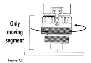
Confused? Try this test. Remove the micrometer and nosecone assembly completely and insert a cutter. Now try to change the depth. Without the micrometer, the only way to move the cutter up and down would be to loosen the spline screw in the cutter knob. Depth control would be nothing more than guesswork.
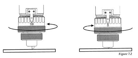
When the cutter is installed into a spindle that has a micrometer depth will be controlled by rotating the micrometer clockwise or counter-clockwise as required. This action exposes more or less of the cutter with each turn. (See Figure 7.2). To remove the guesswork in setting the "proper" depth, we must first "zero" the cutter. Zeroing the cutter allows us to know our starting point and all changes after that can be managed. Once you grasp this idea, the rest is easy.
ZEROING THE CUTTER
To properly zero the spindle and cutter before setting the depth of cut, you will need to:
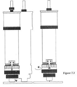
- If you look carefully, you will see that there are numbers and divisions on the spindle micrometer. Turn the micrometer ring to zero. This provides a reference starting point for setting the depth accurately. The micrometer should be threaded onto the spindle housing sufficiently to prevent excessive play in the micrometer and nosecone. If there are too few threads holding the micrometer in place, it will move during engraving. The best starting position is one to three complete revolutions from the top. In other words, take the micrometer to its uppermost position and back it off one to three turns depending on how deep you will need to engrave. (See Figure 7.3)
- CAUTION: When you loosen the set-screw in this step, the cutter may fall out of the spindle and a broken tip is possible. Use one hand to hold the cutter before loosening. With the appropriate cutter installed in the spindle, loosen the spline screw in the brass cutter knob with a spline wrench, more commonly referred to as the cutter wrench.
- Gently place a piece of metal (brass preferred) against the nose-cone so as to push the cutter even with the bottom of the nosecone. Now the cutter should be flush with the nosecone. Tighten the spline screw. The spindle is zeroed and you're now ready to set the cutting depth.
- To select the depth of cut, turn the micrometer to the right (counter-clockwise). Each click equals .001". Therefore, each complete rotation of the micrometer from 0 back to 0 equals .025”. Dial in the depth that will cut through the cap layer to sufficiently expose the core plastic, usually .003" to .012".
ZEROING COLLET TYPE SPINDLES
If you've purchased a collet spindle be sure you feel comfortable with the above process for normal depth setting.
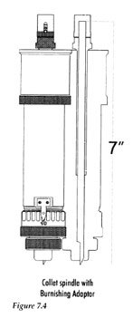
For top-load cutters use a solid collet. Tighten the draw-bar before loading the cutter from the top. The cutter should easily be inserted into the spindle. Once inserted, the procedure for zeroing the cutter is the same as any top-load spindle. In fact, you can even use the burnishing adapter with a solid collet. The only thing you need to check is that you have enough cutter length when the adapter is attached. Most suppliers of cutters sell a 7" length. The reason for this is that when the adapter is added to the collet spindle, it is usually mounted to the top of the draw-bar which increases the overall length. (See Figure 7.4)
You cannot burnish using an adapter if you have a split collet. The collet would grab the cutter and it could not float in the spindle shaft. If you want to use a split collet to hold a top-load cutter, an extra step must be done to insure proper set-up. It's a little tricky for the following reason: When a cutter is inserted into the collet spindle, the draw-bar is loose and the collet is not fully seated. Upon tightening, the collet will be drawn into the spindle shaft and the cutter will be drawn up as well. If you insert the cutter into the draw-bar and do not loosen the brass cutter knob spline screw first, you cannot let the cutter be drawn into the spindle and will never get the draw-bar and collet tight. Letter quality will suffer and the cutter or collet may come loose during engraving.
To avoid this problem, follow these steps:
- Load the cutter from the top with the draw-bar loose.
- Loosen the brass cutter knob spline screw.
- Tighten up the draw-bar to capture the cutter in the collet.
- Retighten the brass cutter knob spline screw.
You are now holding the cutter by both the collet on the bottom and the cutter knob on the top. This is a good set-up and will result in good letter quality.
For bottom-load, short-shank cutters such as end mills, router bits or drills, the split collet is necessary. Load the cutter from the bottom with the draw-bar loose. Tighten the draw-bar. Many applications, such as deep cutting metals can, and in many cases should be done, without a nosecone. If you want to use the nosecone for depth control, a little extra set-up is required. Setting the surface accurately to control the depth is the real chore. The set-up of the engraving table will depend on the manufacturer's hardware, electronics and software. (See Figure 7.5)
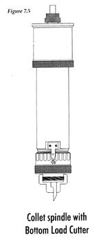
Remember that any time you tighten the draw-bar you draw the cutter up into the spindle. If you use the standard method for zeroing the cutter you will think that the cutter is flush with the nosecone, but the act of tightening the draw-bar has changed the physical location of the cutter by a few thousandths of an inch. When you start the job, you will be surprised to find that the cutter was up inside the nosecone and you did not even break the surface regardless of the depth you dialed in on the micrometer.
Here’s what you need to do to solve this little problem:
- Do your best to set-up using the normal zeroing method. At least the cutter will be within a few thousandths from zero.
- Carefully place a piece of scrap brass under the nosecone and turn the micrometer counter-clockwise until you can just scratch the plate. When you do scratch the plate, back it off .001" and call that zero, your new starting point. Your micrometer will not be set at zero and you will need to note where it is in order to set the desired depth later.
The reason I recommend brass is so that I can easily see the scratch and avoid breaking a fine cutter tip. This isn’t an elegant approach but it’s quite effective and allows for the use of the micrometer to set the depth reasonably accurately. As long as you know where the micrometer was located when you determined you had zeroed the cutter you can add the proper depth by counting the clicks of the micrometer.
SETTING UP YOUR PLATE OR MATERIAL TO BE CUT
I only mention setting up your plate at this point to remind new engraver operators that properly securing the work piece will ensure better results. I've made the mistake of having all other set up procedure down pat only to forget to tie my work to the table. For some strange reason we miss the obvious. Every, and I do mean every engraver has cut into their engraving table. This is usually a result of having the material move during the process. Check and double check this step whether you use a work holding vise or tape. When the object moves, it will probably be scrap.
New products are available to help keep material down on your engraving table, Fat-Mat and Seklema.
It's finally time to explore each engraving technique in its proper detail.
The Engravers' Bible © 1999 by Rich Zydonik/National Business Media, Inc. Printed and Bound in the United States of America. All rights reserved. No part of this self-study manual may be reproduced in any form without permission in writing from the author/publisher. Additional legal, financial and professional management advice and/or assistance are encouraged.
